Linksys WRT54G & WRT54GS power supply
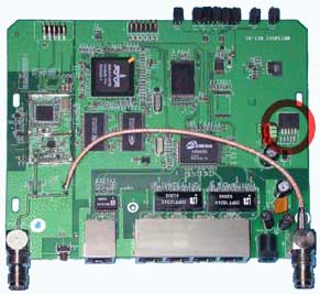
The Linksys WRT54GS v1.0 board has a DC/DC converter which converts the 12V down to 3.3V needed for the router hardware. The DC/DC converter is the 5pin little SMD part near the electrolytic capacitors (shown in the red circle in the image below). It is the AC1501-03 from Anachip Corp., an integrated 150kHz step-down switching regulator with thermal and over-current protection. It works with a supply voltage between 4.75V-40.0V and gives a stabilized 3.3V @ 3A.
That means that the lower limit of the supply voltage is about 5V but the upper limit is much less than 40V. That's because the input capacitor is rated at 25V, so I would not suggest running it on more than 20V.
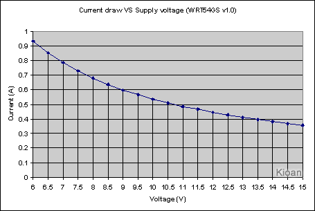
I connected a variable power supply on my WRT54GS to take some measurements and here are the results. Unfortunately the power supply I used (Agilent E3620A) has current limit at 1A so I couldn't go below 6V. During the test the router was idle.
| Supply Voltage (Volts) |
Supply Current (Amperes) |
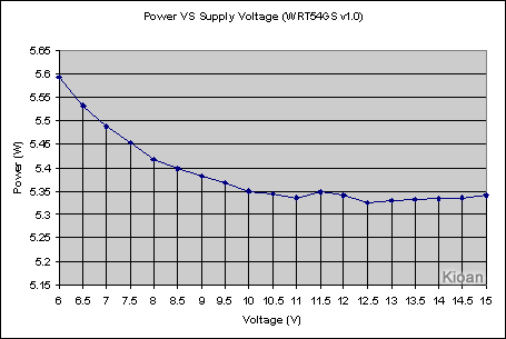
Supply Power (Watts) |
| 6.0 | 0.932 | 5.592 |
| 6.5 | 0.851 | 5.5315 |
| 7.0 | 0.784 | 5.488 |
| 7.5 | 0.727 | 5.4525 |
| 8.0 | 0.677 | 5.416 |
| 8.5 | 0.635 | 5.3975 |
| 9.0 | 0.598 | 5.382 |
| 9.5 | 0.565 | 5.3675 |
| 10.0 | 0.535 | 5.35 |
| 10.5 | 0.509 | 5.3445 |
| 11.0 | 0.485 | 5.335 |
| 11.5 | 0.465 | 5.3475 |
| 12.0 | 0.445 | 5.34 |
| 12.5 | 0.426 | 5.325 |
| 13.0 | 0.410 | 5.33 |
| 13.5 | 0.395 | 5.3325 |
| 14.0 | 0.381 | 5.334 |
| 14.5 | 0.368 | 5.336 |
| 15.0 | 0.356 | 5.34 |
No need for a Power over Ethernet kit!
Worst case scenario: If you have 100m of ethernet cable (UTP cat5e 24AWG) going to your router and give 12V using 2pairs, there is a voltage drop about 5V across it. That means that there are 7V at the other end which are enough for the router to work ;-)
Differences between hardware versions
As far as I know the WRT54GS v1.0 and the WRT54G v1.1 use the same voltage regulator. I am not sure for the other hardware versions so before trying anything of the above, open your router and check it.